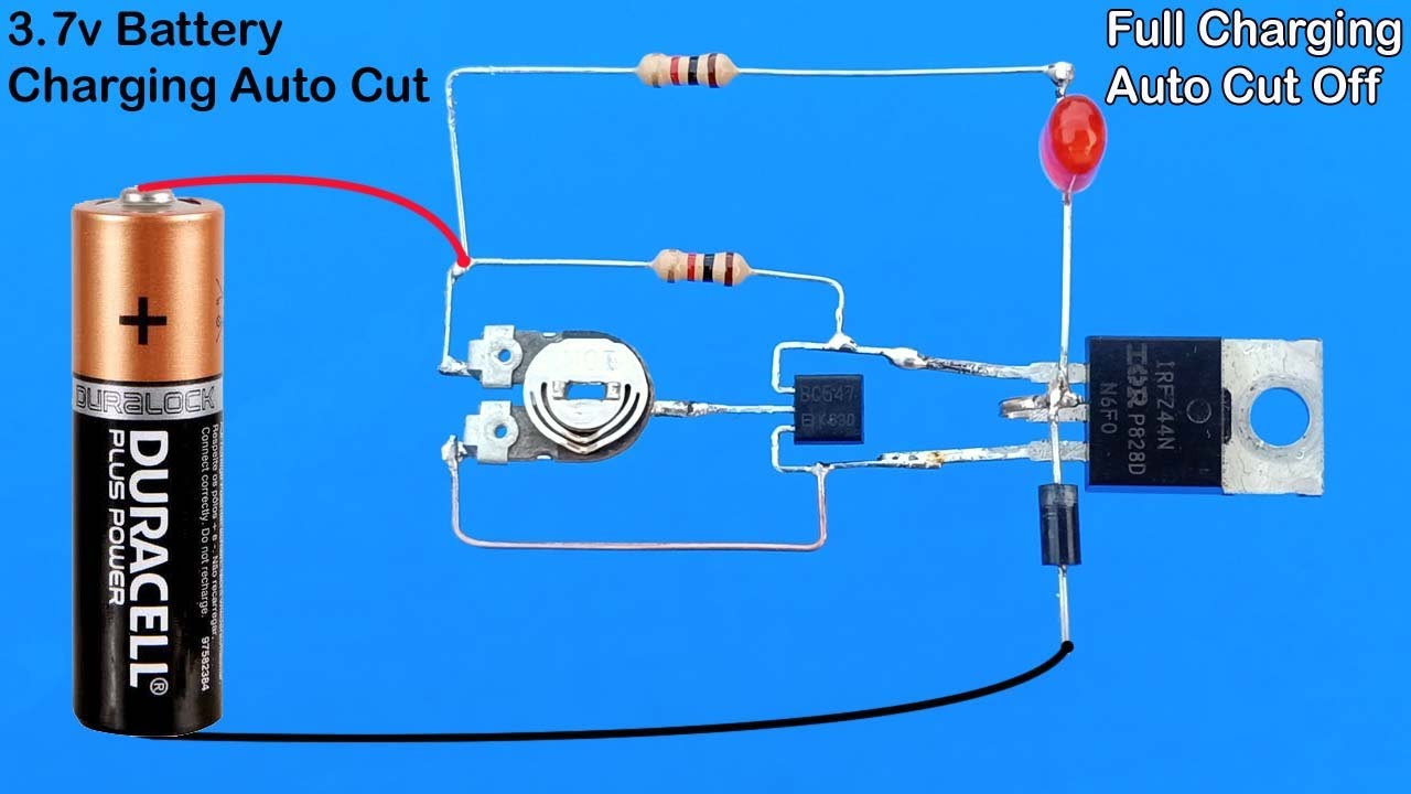
No IC | No Transistor | Automatic 3.7V Battery Charger Circuit
Welcome to my channel "Tech help" here you will learn how electronics is work..Here you will also learn to make diy electronics circuits, handmade crafts, new inventions, mechanical, computer software..Here you will find lots of electronics projects and handmade circuits..
Friends in this video we will learn how to make 3.7v automatic battery charger circuit..3.7v battery charger circuit diagram..3.7v battery charger kaise banaye..Simple 3.7 volt battery charger with auto cut off..Very Simple 3.7v -ion Battery Charger..Auto cut off charging module
Today I am going to make a circuit of 3.7V Battery low and full charge indicator.
Firstly we have to connect 1K resistor to Base and emmiter pin of the transistor as solder in the picture.
Next solder 220 ohm resistor to collector pin of the transistor as you can see in the picture.
Next we have to connect 1K resistor again.
Solder 1K resistor in series to 220 ohm resistor as solder in the picture.
Next connect 1N4007 Diode to the circuit.
Solder -ve of Diode to base pin of Transistor as picture.
Next Solder +ve leg of green LED to 1K resistor which is connected to collector pin of transistor and
solder -ve pin of green LED to +ve of diode as you can see in the picture.
Next Solder +ve leg of Red LED to Collector of transistor and
solder -ve leg of Red LED to -ve of diode as solder in the picture.
Now our circuit is completed and now we have to check this circuit.
Connect +ve of 3V battery to +ve leg of green LED and -ve of 3V battery to emmiter pin of the transistor as you can see in the picture.
~ As in abouve picture glowing Green LED Because this battery is fully charged.
When I connected 3V battery then Red LED is glowing and Green LED is also glowing in small amount.
~ Hence when Battery will be full charge i.e. 3.7V then Green LED will glow only and when battery will be low i.e. 1.5V then Red LED will glow only.


No comments:
Post a Comment