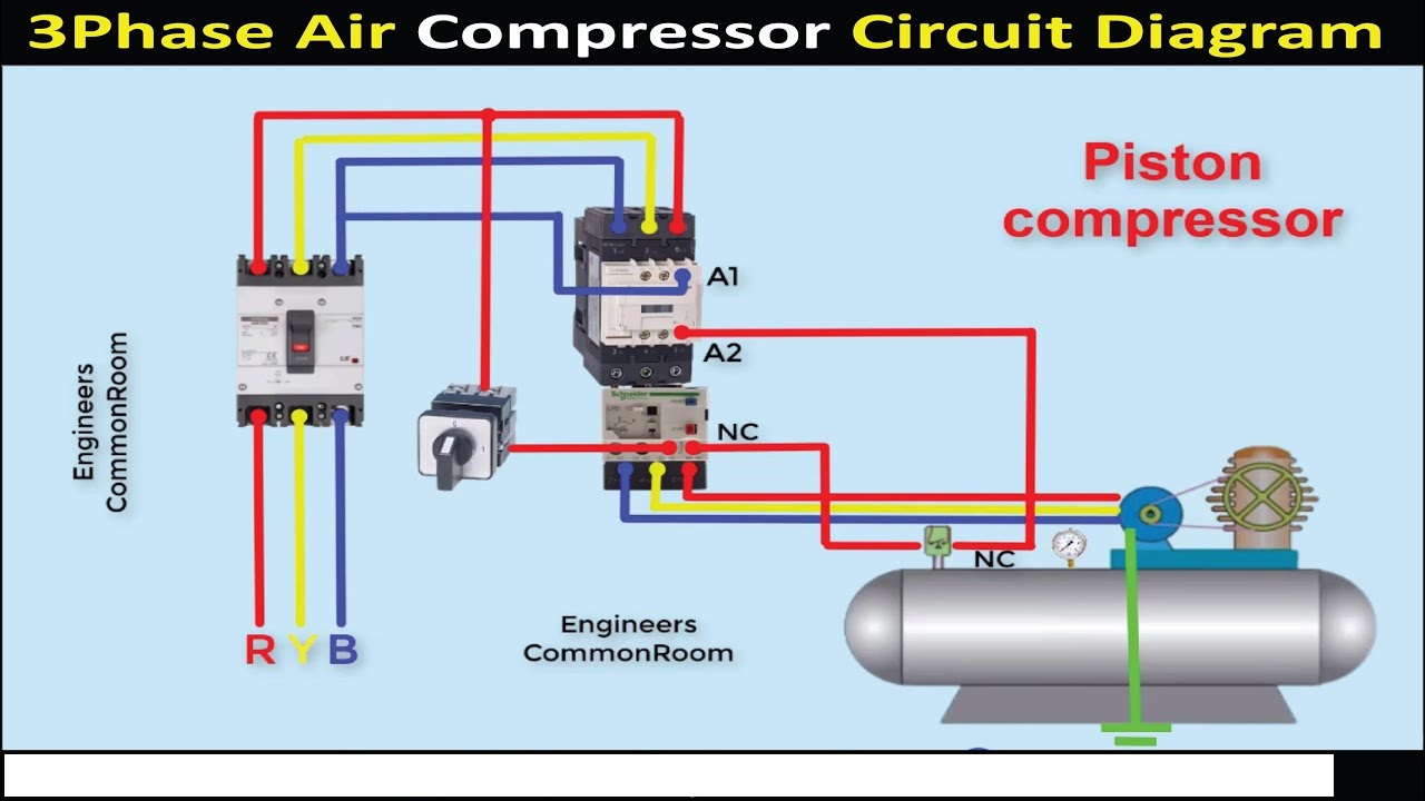
The compressor can be run individually in manual or automatic mode.
PLC Compressor Control Ladder Logic
Two compressors are to be operated alternately from one AC power supply. If one compressor fails, the other one starts automatically. The compressors can be run individually in manual or automatic mode. PLC executes the control and interlocking of both compressors.
Selector switch is provided for each compressor to select the manual or automatic mode. Separate selectors switches provided for each compressor.
Here two operation modes are used for compressors. Manual mode and auto mode.
In manual mode operation by selector switch of each compressor. Compressor 1 can be started by selecting its selector switch and compressor 2 can be started by selecting its selector switch.
In auto mode operation, auto mode selector switch of each compressor should be selected. If one compressor is not working then the second compressor will start automatically.
Here we considered enable command and start contactor for each compressor.
Ladder diagram for Compressors to run individually in manual or automatic mode
Program Description
Network 1:
If auto/manual switch is selected, auto mode selection (M0.0) is ON.
Network 2:
If auto/manual switch is not selected, manual mode selection (M0.1) is ON.
Network 3:
Compressor 1 contactor (Q0.0) can be started either selecting manual mode or auto mode.
Network 4:
Compressor 1 enable command (Q0.1) will be ON in auto mode and manual mode.
Network 5:
Compressor 2 contactor (Q0.3) can be started either selecting manual mode or auto mode.
Network 6:
Compressor 2 enable command (Q0.4) will be ON in auto mode and manual mode.
Network 7:
Fault indication lamp (Q0.5) will be ON if pressure monitor input (I0.4) is activated.
Network 8:
Fault lamp (Q0.5) can be acknowledged by pressing acknowledged button (I0.5).
Network 9:
If pressure is not ok, pressure indicator lamp (Q0.6) will be ON and it will be OFF after 5s if in healthy condition.
Above application may be different from actual application. This example is only for explanation purpose only. We can implement this logic in other PLC's as well. This is the concept of different compressors control in auto mode and manual mode, we can use this concept in other examples as well.


No comments:
Post a Comment