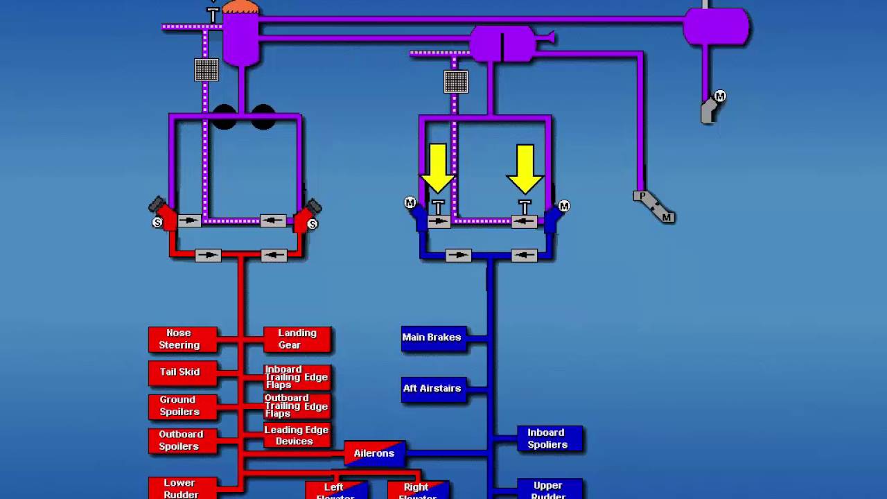
System consists of a single reservoir . Hydraulic power is supplied to the A system from two engine driven pumps fitted to engines No1 and No2 . The pump switches control solenoid operated blocking valves, with the switches on, normal pump output is supplied to the system. A small portion of the fluid that enters the pump is circulated through the pump case for cooling and lubrication. As long as the engines are operating regardless of the blocking valve position this small amount of fluid leaves the pump and is cooled by a heat exchanger in the No3 fuel tank heat exchanger before being returned to the system.
fluid shutoff valves controlled by there respective switches control the fluid in the engine pump supply lines, when closed fluid flow to the pump is isolated. (includes lubricating and cooling fluid). pulling the fire switch on engine 1 or 2 will close these shutoff valves, the fire switch also deactivates the low pressure warning light.
System A and therefore system B and stand by reservoirs are pressurized by engine bleed air from engines 1 & 2 this is applied to the reservoir to ensure a positive supply of fluid to the pumps.
A balance line connects the system A reservoir to the system B reservoir at a level of 2.5 gall.


No comments:
Post a Comment